
What Is a Welding Robot and Which Welding Processes Does It Run?
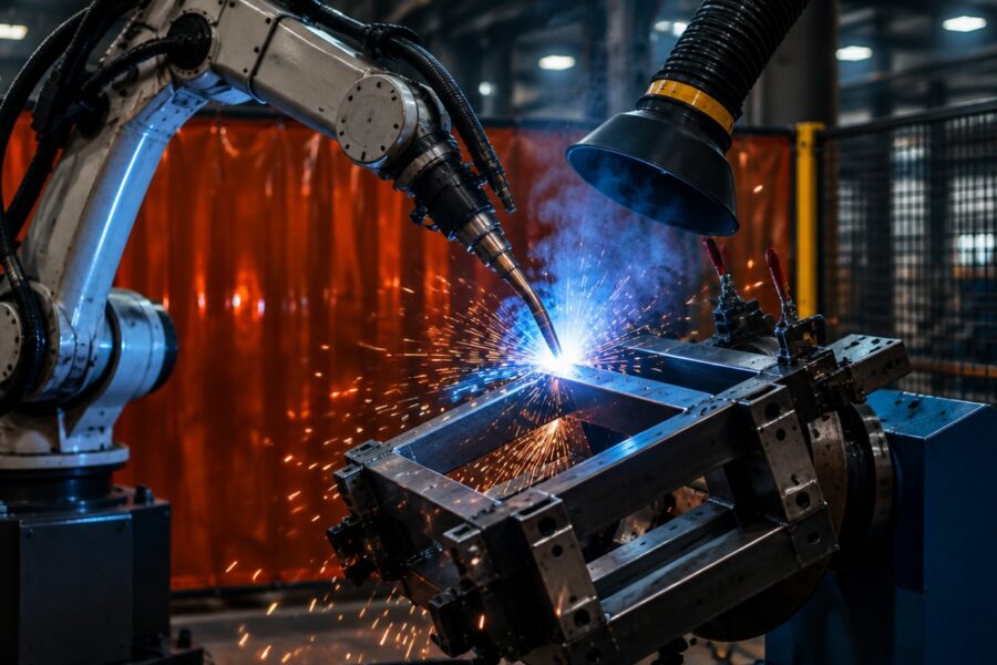
A welding robot is an industrial robot arm with a welding torch mounted on its wrist, communicating with a welding power source. The robot only carries the torch; what actually makes the weld is still the parameter set made up of current, voltage, wire feed speed and travel speed. The value the robot adds is that it repeats those parameters and that torch path identically on every part.
The most widespread industrial use is gas metal arc welding (MIG/MAG). TIG is used on materials such as aluminium and stainless steel, resistance spot welding on sheet assemblies, and laser welding on thin sheet and in work that demands high speed. Each process loads the robot differently: MAG brings wire feed and spatter management to the fore, TIG needs slow and extremely steady travel, and spot welding calls for high payload because of the weight of the gun.
The real advantage of robotic welding over manual welding is not speed but arc-on time ratio. In manual welding only a small share of a shift is actually spent under the arc; the rest goes on handling parts, clamping, changing wire or electrodes, lifting the helmet and resting. In a robotic cell that ratio rises markedly, because while the robot welds at one station the operator can load the other.
For Which Parts and Batch Sizes Does Robotic Welding Make Sense?
Robotic welding has traditionally been economical on parts that are repetitive and geometrically stable. Three questions drive the decision: how many of this part are produced per year, how many metres of weld does the part carry in total, and how long does clamping it take?
On a part with a short total weld length and a long clamping time, the robot spends most of its time waiting, and the gain is limited. Conversely, on a chassis component with long seams and multiple passes the robot is under the arc almost continuously, and the difference becomes dramatic.
The factor that has lowered the batch-size threshold in recent years is offline programming. Generating the program from the three-dimensional model of the part, instead of teaching the robot by hand at the cell, shortens changeover time on small batches and frequent product changes. We covered the effect of that approach on commissioning risk in our article on zero-risk automation setup with simulation.
Field note: The judgement “we produce in small numbers, so it does not suit us” is usually made from the wrong starting point. What matters is not how many of a single product are made, but the total volume of the product family that can be clamped in the same fixture. If five parts of similar geometry can be welded in one clamping arrangement, the cell is full even when the individual quantities are low.
What Does a Robotic Welding Cell Consist Of?
The investment is not, as many assume, “a robot plus a torch”. A working cell contains all of the following:
- Robot arm and controller: welding generally calls for 6-axis models with moderate payload and long reach.
- Welding power source and wire feeder: digital communication with the robot controller is critical, so that parameter sets can be called from the program.
- Torch and collision protection: neck geometry determines accessibility directly; a collision sensor protects the torch and the robot in a crash.
- Fixture: the component of the cell that is most decisive for quality.
- Positioner: rotates the part into a suitable welding position.
- Torch cleaning station: nozzle cleaning, anti-spatter spray and wire cutting; a precondition for stability over long shifts.
- Fume extraction and safety perimeter: arc screens, safety fencing, interlocked doors and light curtains.
Which robot class these components pair with follows from the weight of the torch package and from the furthest seam that has to be reached. How payload and reach are verified is explained step by step in our article on choosing the right robot: payload, reach and cycle time.
Why Is Fixture Design More Decisive Than the Robot?
This is the surprise most often encountered by businesses moving to robotic welding: what determines the success of the project is not the robot brand but how the part is clamped.
The reason is simple. The robot repeats the path it was taught with the same precision every time; whether the part arrives underneath that path in the same position every time is decided by the fixture. If the clamping tolerance is loose, the seam shifts, the arc gap changes, and the result varies from part to part. In manual welding the operator compensates for that deviation instantly; the robot does not.
The second issue is thermal distortion. The part heats up and shrinks during welding; if the clamping arrangement does not account for that shrinkage, the part either seizes in the fixture or ends up out of final tolerance. This is why the welding sequence — which seam pulls first — is designed together with the fixture.
The third issue is access. Clamps, toggles and stops must not obstruct the area the torch has to reach. These conflicts have to be checked not on paper but in a three-dimensional environment with the real kinematics of the robot; the single biggest time sink on the floor is an access problem discovered after the fixture has been manufactured.
Is a Positioner Necessary, and How Many Axes Are Enough?
A positioner is an auxiliary axis that rotates the part to bring the seam into the most suitable position for the robot. Whether it is needed comes down to a single question: can the seams be welded in one clamping, in the flat position?
On a box-shaped part with seams on all four faces, a solution without a positioner forces the robot into strained angles. Those angles both approach the limits of its reach and degrade weld quality. A single-axis turntable is enough in most cases; when the part has to be both rotated and tilted, a two-axis positioner comes into play.
In efficiency terms the real gain lies in two-station (rotating partition) arrangements. While the robot welds on one side, the operator unloads and reloads on the other. Clamping time is taken out of the cycle time and the robot’s arc-on time rises noticeably. The logic is the same as one robot serving more than one station; we worked through a comparable calculation in our article on how many CNC machines a single robot can run.
On long parts, a linear track (a seventh axis) comes onto the agenda instead of — or alongside — a positioner, with the robot travelling along the part.
When Does Seam Tracking Become Mandatory?
A robot follows the path it was taught. Incoming parts, however, are not always identical: laser cutting tolerance, bending deviation, distortion left by earlier welds and differences in clamping can shift the real position of the seam away from the programmed one. Once the deviation exceeds a certain threshold, the robot welds into the air or onto the edge.
There are two families of solution here. The first is touch sensing: before welding, the robot touches the wire or the nozzle to the part, measures the real position and shifts the program. It is inexpensive, adds cycle time and requires a clean part surface. The second is real-time tracking: the seam is followed during welding, either through the arc (through-arc weaving) or with a laser sensor, and the path is corrected on the fly.
The decision criterion is clear. If part tolerances are tight and the fixture is solid, a tracking system may not be needed at all. In heavy-section, multi-pass fabrication with wide tolerances, tracking is not an option but a precondition. Before enlarging the investment, the right step is to measure the actual size of the deviation — very often the problem can be solved in part preparation, and the sensor becomes unnecessary.
How Is Quality Made Repeatable in Robotic Welding?
A robot does nothing but accelerate a bad welding procedure. The first step is therefore to write down the parameter set: current, voltage, wire feed speed, travel speed, gas mixture and flow rate, torch angle and weave amplitude. That set is recorded as a welding procedure specification and validated on sample parts.
The second step is consumable and hardware stability. Nozzle contamination, contact tip wear, a blocked wire liner and fluctuating gas flow all affect arc stability directly, and the robot cannot compensate for any of them. A torch cleaning station together with disciplined consumable replacement determines the quality and the availability of the cell at the same time.
The third step is traceability. Modern power sources can record the current and voltage curve of every seam and flag deviating cycles. Once that data is transferred to a production management system, a quality record is created per part. We described how that data integration is arranged in our article on integrating MES with robotic systems.
Finally, competence: in robotic welding the operator’s role shifts from holding the torch to managing the program and the parameters. This does not remove the need for a welder; it moves welding knowledge to the head of the program. If the person running the cell does not understand welding, there is nobody left to diagnose a deviation.
Which Items Determine the Price of a Welding Robot?
There is no single answer to the question “how much does a welding robot cost”, because what is bought is not a robot but a cell. The items that set the cost are:
- Robot class: price rises as reach and payload increase.
- Welding process and power source: TIG and laser applications require a higher investment than a standard MAG installation.
- Positioner and number of stations: a two-station rotating arrangement costs more than a single station but raises cycle efficiency.
- Number of fixtures: every product in the family needs its own clamping arrangement; in multi-product businesses this item can exceed the robot itself.
- Tracking and sensor systems: touch sensing is relatively economical, laser tracking noticeably costly.
- Safety, extraction and infrastructure: fencing, arc screens, fume extraction, power and gas supply.
- Programming and commissioning: this item grows as part variety increases.
When making comparisons, the only correct unit is the total cost of the cell converted into a cost per metre welded or per part. How the return on the investment is constructed is covered in our article on the payback period for automation investments, and where the gain actually shows up is covered in our article on calculating OEE.
How Are Fume Extraction, Arc Screens and the Safety Cell Arranged?
A welding cell carries two risks beyond those of a standard robot cell: arc light and welding fume. Because arc light can cause eye damage to people working nearby, arc screens or opaque panels are applied around the cell. Welding fume contains particulates released during welding; an extraction system positioned close to the weld point is far more effective than general ventilation.
On the mechanical safety side the arrangement is the same as in other robot cells: perimeter guarding, interlocked doors, a light curtain at the operator station, and separation of the zone behind the rotating partition in two-station layouts. Which standards the risk assessment follows, and how cell safety is documented, is set out in detail in our article on ISO 10218-1/2 safety standards.
Field note: The point most often skipped in two-station cells is that the physical separation on the side where the operator is loading is not sufficient against arc light and spatter. The centre panel of the rotating partition must be designed to close off both light and spatter completely.
The Most Common Mistakes When Moving to Robotic Welding
The first is leaving the fixture budget until last. When the robot is ordered and the fixtures are left to “sort out later”, the project usually stalls at exactly that point.
The second is leaving part preparation unchanged. Cutting and bending deviations that are tolerated in manual welding come straight back as defects in robotic welding. In most projects the cheapest improvement is not adding a sensor but tightening upstream manufacturing tolerances.
The third is designing the cell around a single product. When a new product family arrives two years later and does not fit the cell, the investment loses half its value; the dimensional envelope of the product family should be considered from the start.
The fourth is failing to set up a consumables and maintenance plan, and the fifth is not carrying welding knowledge into the cell. How maintenance discipline is established for long-term cell performance is shared in our article on preventive maintenance on industrial robots.
Moving to robotic welding is not a decision to buy a machine; it is a decision to design a process. Whether your part geometry, your product family and your existing layout suit this arrangement can be seen by measurement before the investment: a site survey and simulation step answers those questions numerically. To evaluate the cell design together, look at our project management and simulation services, and for commissioning and beyond see our service and maintenance page.